In close cooperation with our partners we develop mathematical methods and parametrical models to solve complex design tasks. Our solution allows to create extremely intuitive near-production-ready virtual parametrical design. In most cases, the process is fully automated.

The end-goal of our tools is to provide high quality NURBS-surface data. This allows lossless data transfer to any other CAD/CAM system for manufacturing or other purposes. More about our core competences...


Get in touch: contact@icapp.ch.


Software

panelshop - Auto SBC
(Spring back compensation)

panelshop - Auto SBC is a standalone software to help sping back compensation calculations. It can be licensed directly from iCapp or via our distribution partner ESI Group
More about the product...


covermesh and
covermesh for Rhinoceros
(fully automated procedure for reverse engineering tasks of organic shapes)

covermesh is a standalone software with a very simple GUI, used to define files and settings. The software is optimized to run in a batch mode. The covermesh library can be integrated to your digital workflow, so that it is called automatically by a script. covermesh for Rhinoceros is a Rhinoceros (a popular CAD software) plug-in.
More applications...


rhinoreverse for Rhinoceros
(semiautomatic tool for reverse engineering)

rhinoreverse is a Rhinoceros plug-in.
3D triangle meshes (STL-format) can be transformed to NURBS-surfaces. The user simply draws wide surface boundaries, and the software does the rest! A unique break-through feature offered by the software is the ability to calculate the trimmed surfaces.

rhinoreverse may be ordered from iCapp or via 66 international dealers.
More about rhinoreverse...


rhinoCWK for Rhinoceros
(Interface: Rhinoceros & Cadworks)

rhinoCWK is a Rhinoceros (a CAD software) plug-in. The software allows bidirectional transfer of detailed design data.
More about rhinoCWK...


PAM-DIEMAKER for Catia V5
(Die face design)

PAM-DIEMAKER for CATIA V5 is a plug-in for CATIA V5 to help die face design in car body construction. For questions and licensing please contact our development and sales partner ESI Group.
More about the product...
Download the product flyer


FASTTRIMSTEEL for Catia V5
(Trim steel design)

FASTTRIMSTEEL was developed to easily and rapidly design trim steels (cutting blades) in Catia V5. For questions and licensing please contact our development and sales partner Cenit AG Systemhaus.
More about the product...
Product development history...
Download the product flyer


Services
for complex NURBS surface design

The Image shows a high-performance racing boat....

Complex boundary conditions can make NURBS surface design challenging. General purpose CAD software can’t often be used for such special purposes.

Together with our customers and partners from a range of fields like Architecture, Product Design, Medical Technologies, Automotive or Engineering Industry, we develop special purpose molds.

The various projects, we are involved in share a common requirement: the need to design smooth NURBS surface models for manufacturing purposes. Some of the recent special projects are...


We’ve also developed a number of additional custom software components. We utilize these components to help clients successfully complete their custom projects.
Some examples are described here...

Additional software-based solutions


Detailed description of our software


Auto SBC is an abbreviation for "Automated Springback Compensation". The software allows to transform a set of given trimmed NURBS surfaces into their resultant deformed mesh surface. The tool can also be used for other similar applications (e.g. compensation of elastic mold bending).

To use the software, a vector field or two compatible mesh surfaces (internally used to calculate the vector field) must be provided.

Auto SBC has been designed to be used in combination with FE-software like PAM-STAMP, AUTOFORM or LS-DYNA. The FE-analysis is used to determine the resultant surface of the compensated mold represented by a mesh surface. The data, provided by FE-software tools are used as the input for Auto SBC.

Benefits

  • Once the input data is provided, the procedure is fully automatic.
  • Rapid calculation. The time required to calculate the surface transformation of the part shown in this video (Front hood of DaimlerChrysler) is just 3:08 min.
  • High quality surface data: Accurate representation of the deformed mesh. “Skinnable” (transition tolerance of 0.01 mm) surface model.
  • Very easy to use. Just half an hour of training time is enough to get started.
  • Fixed surfaces that have not been modified within the FE-optimization process will remain unmodified.
  • Symmetry is supported.
  • Robust extrapolation algorithms allow the software to be used for spring forward analysis.
Advanced global calculation approach makes the software highly robust when dealing with inhomogeneous and incomplete data. Thus, the software automatically solves the three most frequent problems:
  • The vectors do not have to start exactly at the CAD surfaces.
  • The vector field can be inhomogeneous and may have arbitrary holes. (in this case, the existing vectors parameters will be used for interpolation)
  • The vectors do not have to define the entire part; a partial coverage is sufficient (as in case of any spring forward analysis). In such cases, the outer regions of the die may also be transformed using a slightly abating transformation field.

Development Partner The core procedure has been developed from 2005 to 2009 with the expert support of ESI-GROUP. It has been tested and optimized with PAM-STAMP/OUTIFO.

Links
Video: Compensation of a front hood (DaimlerChrysler) 3:08 min


Special features

  • Fully automatic:
    Triangle meshes (STL-format) are imported and NURBS-surfaces (IGES-Format) are calculated and exported in IGES-format.
  • Optimized to be used in batch mode:
    covermesh can be supplied as a library to be integrated into your digital process to be called directly by any script.
  • Simple Windows interface:
    A very simple simple GUI lets operators run covermesh with a set of specific parameters.
  • Plug-in for Rhinoceros:
    covermesh for Rhinoceros may be called directly from within a CAD system. The resulting surface data (NURBS-surfaces) may be integrated directly into any CAD-model.

Additional examples of covermesh and covermesh for Rhinoceros...


RhinoCWK is a plug-in for Rhinoceros. Design data and their attributes can be exchanged between Cadworks and Rhinoceros.

Cadworks is the leading 3D CAD/CAM software for timber construction. Cadworks is used to plan and design the constructions. The production processes are often further defined and planned within Rhinoceros.

RhinoCWK was successfully used on a number of projects, for example for the "Centre Pompidou Metz"...


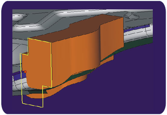
This software tool automatically designs the complex base bodies and all additional working surfaces required to design trim steels used for cutting sheet metal and plastic parts. New calculation algorithms have been developed and implemented to create 3D offset curves and surfaces. The software completely eliminates the need for the time-consuming mutli-stage manual design procedure that was used up until today.

Benefits

  • The workload is reduced by almost 95%! The definition and calculation of all cutting blades for the Porsche side panel (shown above) - now requires less than 2 hours (vs. the 40 hours, it would require without the software).
  • Beside the cutting blade body the working surfaces, required for machining, are also computed automatically. Four different shape types are available to meet any required guideline: The "V”; the "Double V”; the "Straight” and the "Step”-shapes.
  • To satisfy machining conditions the working surfaces are automatically adjusted to prevent collision and backdraft.
  • The guaranteed optimal clearance (oversize) of the created casting bodies, as well as the optimized size of the working surfaces reduces the required machining time to the absolute minimum.
  • Thanks to the automatic procedure, parameters’ calculation is precise and reproducible.
  • The software is very easy to use, only requiring less than half a day training.
Additional Notes
To calculate the features, it is necessary to provide the cutting curve, the die surfaces and the working direction. The user only needs to adjust the dimensions, as required; from this point on, the calculation is done automatically. Parameters for both, the base body (as solid) and the working surfaces are calculated. All the calculated surfaces and bodies may be exported via a number of available converters.


Scrap cutter with a sharp-edged (90°) cutting curve, upper (left) and lower (right)


One of the main important advantages of the software is that it may be used for calculating the parameters of scrap cutting blades (see the image above). Both, the upper and the lower tool (which differ from each other) will be calculated automatically.

Development Partner
Design methods have been developed (2005-2006) with the expert support of the tool maker division of August Läpple GmbH & Co KG.

Publication: "3D Konstruktion von Schneidwerkzeugen für den Karosseriebau", Summer 2005

CATIA V5 - plug-in
CATIA V5 plug-in FASTTRIMSTEEL has been developed in collaboration with CENIT AG SYSTEMHAUS (Gold partner of DASSAULT SYSTEMS). The first version was released in August 2007. In 2008, blades’ segmentation has been implemented. Further developments made since 2009 improved the parametrical design and the handling of cutting blades in FASTTRIMSTEEL (PDF) e.g. by the parametrical design of the cutting blade base body.

Two first hand reports have been provided at the 3rd Forum for Tool Shops, organised by Cenit AG Systemhaus in Stuttgart, Germany, 9. April 08 (available in German language only):
  • Einsatz des Schneidleistenmoduls TSE in der Prozesskette des Audi-Werkzeugbaus, Johannes Möller, AUDI AG.


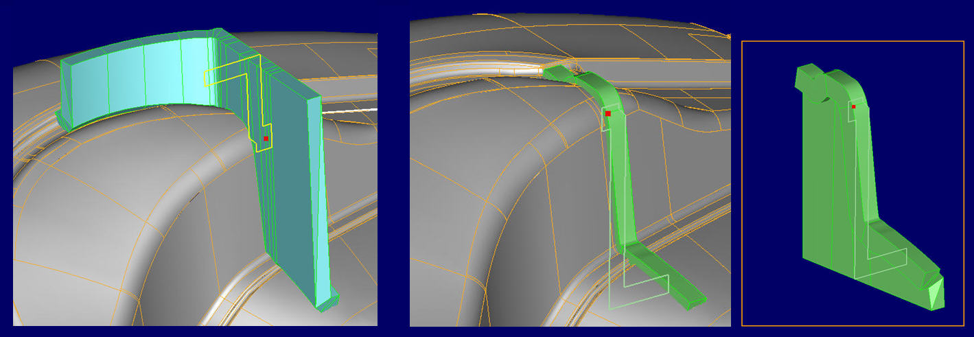
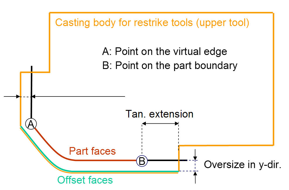
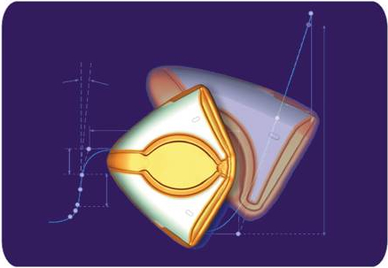
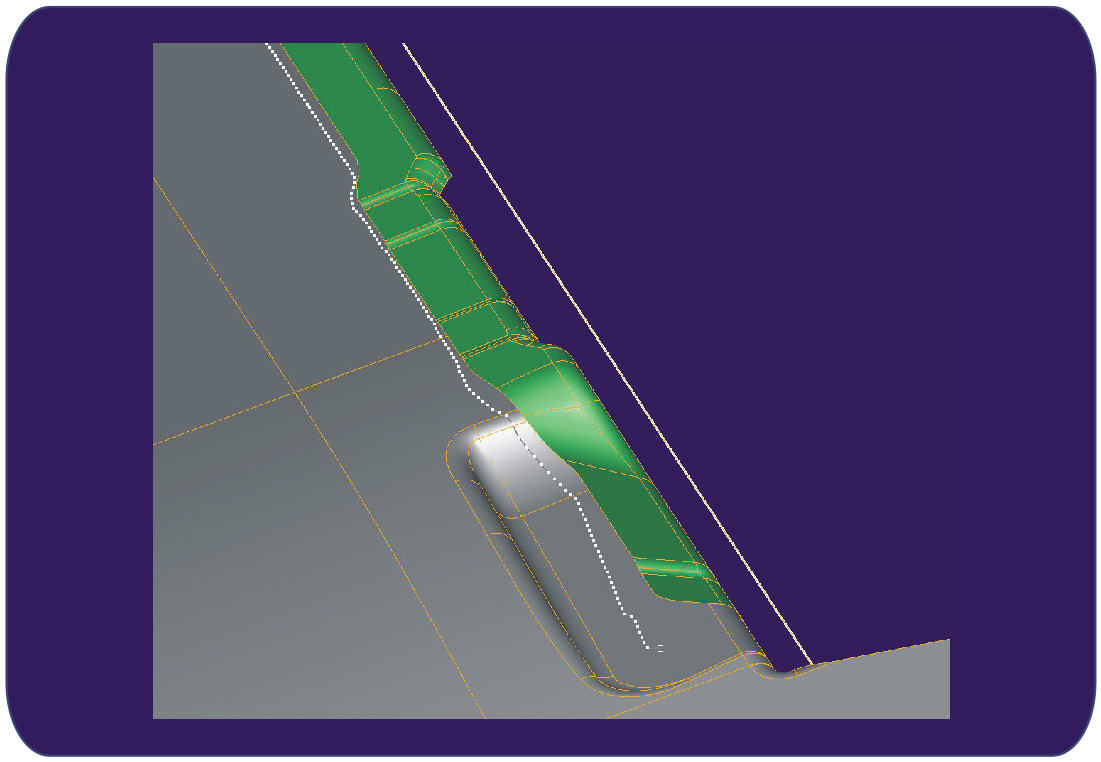
The base body parameters of restrike dies - used for sheet metal parts - are generated automatically. New mathematical algorithms have been developed to handle special conditions: The design is determined by two leading 3d curves, which presented a challenge for automatic calculation (the cutting blades have a single curve). An additional method was developed: a consistent tangential extension for multi-part boundary curves.

Benefits

  • The workload is reduced about 95%.
  • The optimization of the resultant casting body size significantly reduces the required machining time.
  • Thanks to the automatic procedure, parameters’ calculation is precise and reproducible: Casting clearances are also calculated automatically, even for complex geometrical areas.
  • Easy to use. The required initial training is just 2 hours.
Additional Notes

Upper die: Unlike cutting blades, restrike dies are defined by two 3D curves: Curve A, which normally is created by virtual edges (along a chain of blending faces) and curve B that represents the part boundary.


Section of the upper die, curve A and B are displayed as intersection points

To define restrike dies two additional surface operations have been implemented:

  • Tangential extension of the part boundary surfaces (above). The part outer surfaces (curve B) is automatically extended according to the user-defined value. The resulting surface model is “skinnable”.
  • Offset-surface (see picture above). The part boundary surfaces and the calculated extended surfaces are combined to automatically calculate the resultant offset surface. This surface is required to trim the casting body. The use of offset surface ensures the precise and consistent casting clearance.
Lower die: In order to design the lower die, the software calculates tangential surface extensions around the entire part. If the part contains gaps, the software allows to automatically close them.

Development Partner
Design methods have been developed (2006-2009) with the expert support of the mold and die specialist, August Läpple GmbH & Co KG.

Links
Video: Design of a typical upper restrike mold - 5:30 min
Video: Part preparation for the lower restrike die - 1:18 min

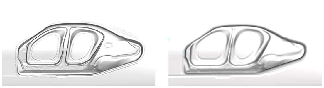
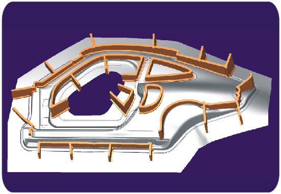
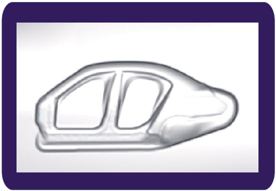
At the early stage of the casting mold and tool design, the software automatically builds offset surfaces with large (around 50 mm) offset distance values. To handle the small offset values within the material thickness, we’ve implemented an additional procedure. The illustration above shows an offset surface (offset distance of 60 mm) for a side panel.

Benefits

  • Fully automated, easy to use
  • Excellent ability to handle holes and gaps in the provided surfaces (and between them)
  • Resultant calculated surfaces have small data footprint
  • Automated calculation of a zero surface (offset distance = 0 mm)
  • Allows using mesh-based data, e.g., from FE-software-tools like DIEDESIGNER (AUTOFORM) or PAM-DIEMAKER (ESI-GROUP) or other similar software.


Zero surface and 60 mm internal offset


Additional Notes
The resultant offset surface (in case of large offset for casting) is represented by a single spline surface. It can optionally be automatically split to arbitrary checkerboard-like segments to optimize data handling for the target CAD-system.

Development Partner These procedures have been developed in 2002, 2003 with the kind support of ThyssenKrupp Drauz Nothelfer.

Publication: "Offset-Flächen vervollständigen die CAE-Kette in der Konstruktion von Grosswerkzeugen für den Karosseriebau", Sommer 2004


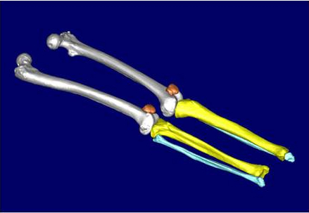
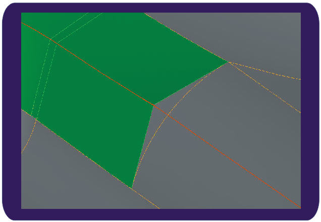
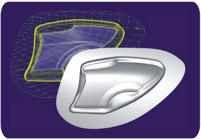
Spline surface models of sheet metal parts often do not contain all base surfaces that are needed to recover virtual edges (also called "theoretical corners"). One such case is when the surface model has not been designed by parametrical methods. This is due to the fact, that the data origin often is a physical clay model. In this case the derived spline faces do not have linked any base surfaces that meet in the virtual edge. Another possible reason is that the base surfaces have been lost due to the translation of the data between several CAD systems.

However, a number of mold design scenarios does require virtual edges as well as the additional surface data on surfaces, which end in those virtual edges, when they meet each other (see figure above). Another similar task (internally using the same algorithms) is rounding radius reduction. This procedure is important for creating so-called "cut outs" in the punch and die designs.

Benefits

  • Extremely simple and intuitive, fully automated
  • The resulting curve segments that define virtual corners are automatically joined into a single continuous 3d curve.
  • Automatic rounding radius reduction by a required distance for a given chain of blending surfaces.


A so called “winding off” method is often used in order to come up with the initial approximation of the required trim curve. As a first approximation of the trim curve. Standard CAD systems do not support such calculation well, which means that the calculation requires a lot of manual work and calculation time.

The current module of panelshop offers a pure geometrical solution to determine trim curves: Flange boundary curves will be winded off in planar sections of any predesigned spine curve onto the surfaces of the die. The result is a spline curve and/or a sequence of points that represents the trim curve.

Benefits

  • Easy to use, no training required
  • Short calculation times


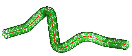
The integrated mesher was developed to mesh any type of CAD-faces. Several options like "edge length" or "normal deviation" can be set to adjust the mesh to the users requirements. The computed meshes can be exported in common FEA formats Data Translater for more details).

To allow FEA to be used for efficient tube bending processes a special tube mesher has been developed.


Tube mesher: Needs the same input data as a bending machine - polyline and radii

In addition to the input of the polyline and the radii the user has to determine the mesh size. A process-adjusted mesh is calculated automatically.

Benefits

  • Easy to use
  • Robust
  • Includes a special tube mesher