

|
Services |
|
|
|
|
|
iCapp develops CAD applications - libraries, with or without GUI - for special purposes in tool design, manufacturing or mechanical engineering in general. We have extensive experience in the calculating of curvature- and process optimized spline-surfaces, depending on arbitrary criteria and boundary conditions. |
|
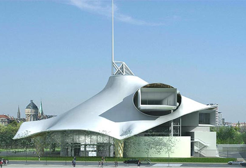
Centre Pompidou Metz c CA2M, Shigeru Ban Architects Europe et Jean de Gastines, image Artefactory |
|
|
|
|
|
|
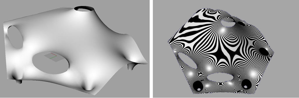
The use of a single NURBS surface (left), enables to optimize the overall smoothness. The illustration on the right shows a zebra-plot of the resulting surface, allowing the designer to assess curvature. In the form. |
|
|

|
|
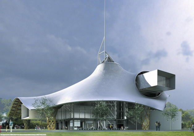
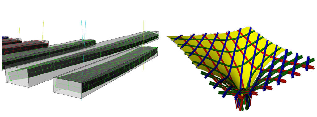
The timber construction comprised 6 layers of wooden beams. Each layer surface was calculated from the first NURBS surface, using a normal offset distance (around 0.4 m). |
|
|
|
|
The length and shape of each beam varies due to the torsion in the layer surface. This causes the ends of the beam to vary (see left figure above). For the project to succeed, all beams have to be manufactured automatically by an NC milling machine. The digital data required to achieve this, is readily available from the 6 layers. |
|
|
|
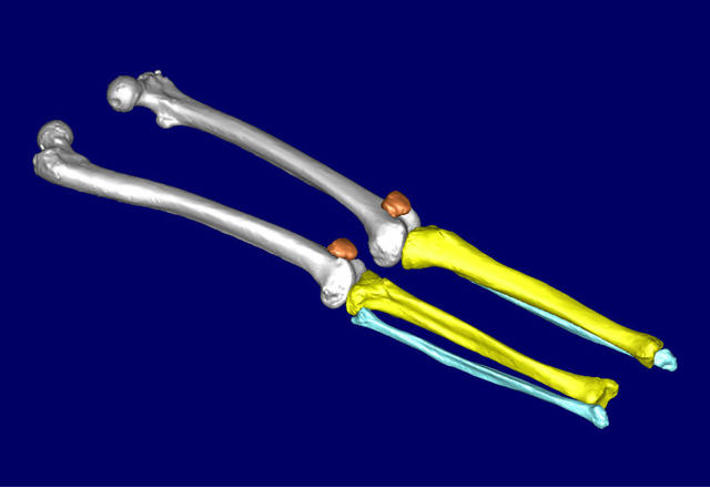
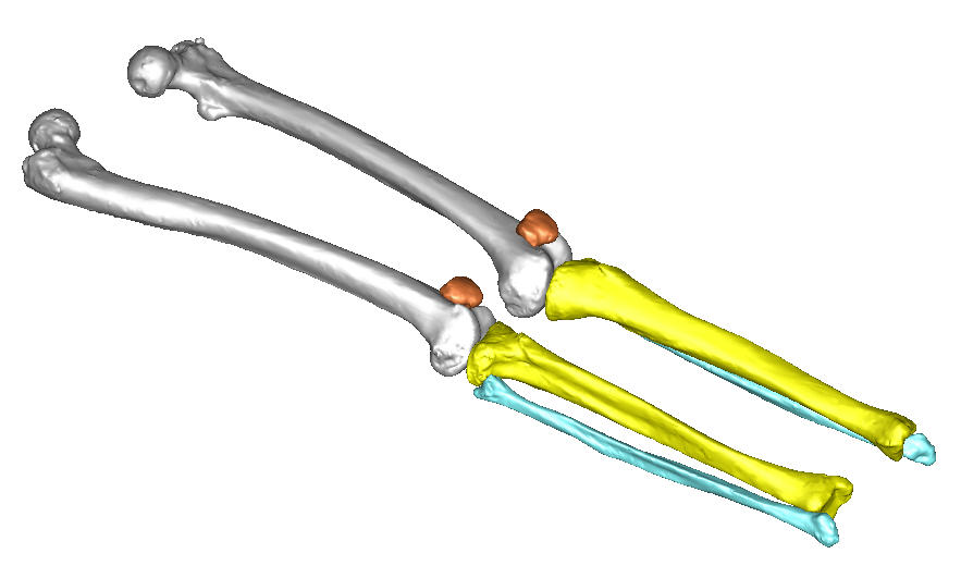
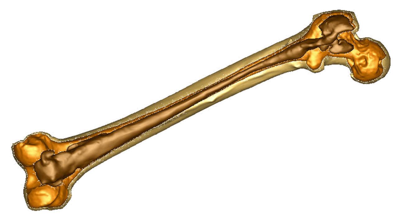
Digitized data of lower human limbs - femur, patella, fibula and tibia - from Stryker |
|
|
|
|
|
|
Surface STL data sets - top left. The resulting NURBS-surface model - top right. The software creates smooth surfaces, bounded by 3 to 15 boundary edges. Most reverse engineering tools can use a maximum of 4 curves to define a surface. Overcoming this restriction was required to solve the design challenge. We were able to adjust the seams within 0.01mm tolerance - to get a waterproof model for each layer. This allowed production of high quality watertight forms. |
|
|
|
|
The image above shows the three layers of the bone (as mentioned above). Usually, transformation of mesh data into NURBS surfaces results in files with a very large size. Our software, however, uses algorithms, which allow the resultant files to be far smaller. For this specific medical application, 200 faces were typically needed to represent one femur bone layer described by approximately 20 000 curvature based triangles derived from the original scan. The file size of the face model is almost the same as the size of the STL mesh file. |
|
|
|
|
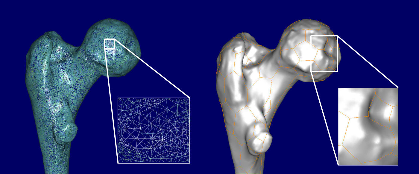
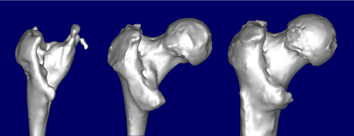
For each tissue layer, NURBS models have been calculated for every given bone. The images above and below show the complexity of the created surface models for the upper and the lower part of a femur. |
|
|

|
|
The advantage of the algorithm used in this application is its ability to allow an approximation to the mesh data to be done for every single face. Each point is calculated with a distance-to-mesh tolerance of 0.1mm. This ensures that all bone details are represented in a smooth surface model. |
|
|
|
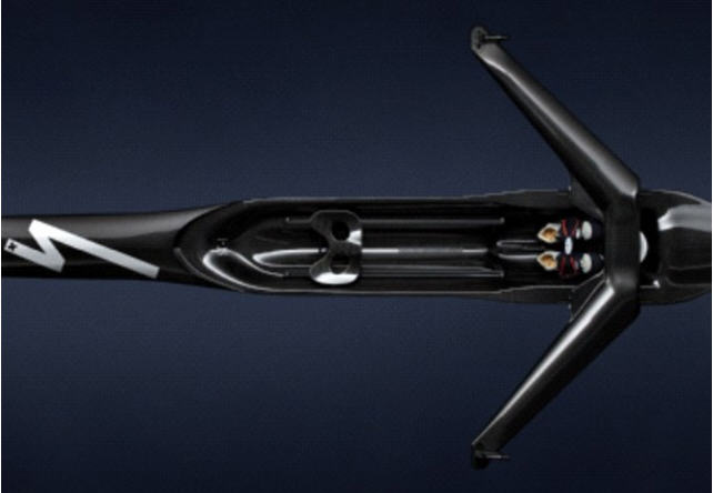
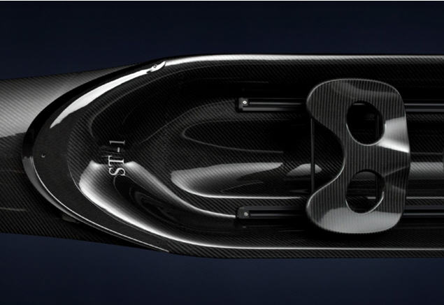
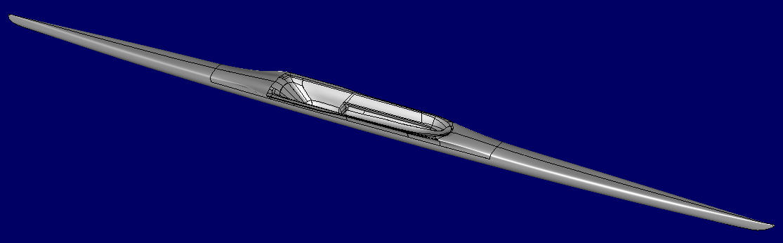
Detail of a composite single scull designed by Stämpfli manufactured by hs composite. |
|
|
|
|
|
|
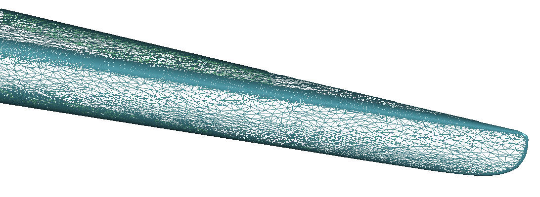
Design development became a blend of traditional “trial and error” methods and the ones utilising technical advances in CAD and CNC control. Experienced highly skilled craftsmen created the initial shape. Professional rowers optimized the 8 m long body of the prototype by several trials. The final shape then was digitized by an optical scanner (ATOS by GOM). The result was a closed triangle mesh (see figure above). |
|
|
|
|
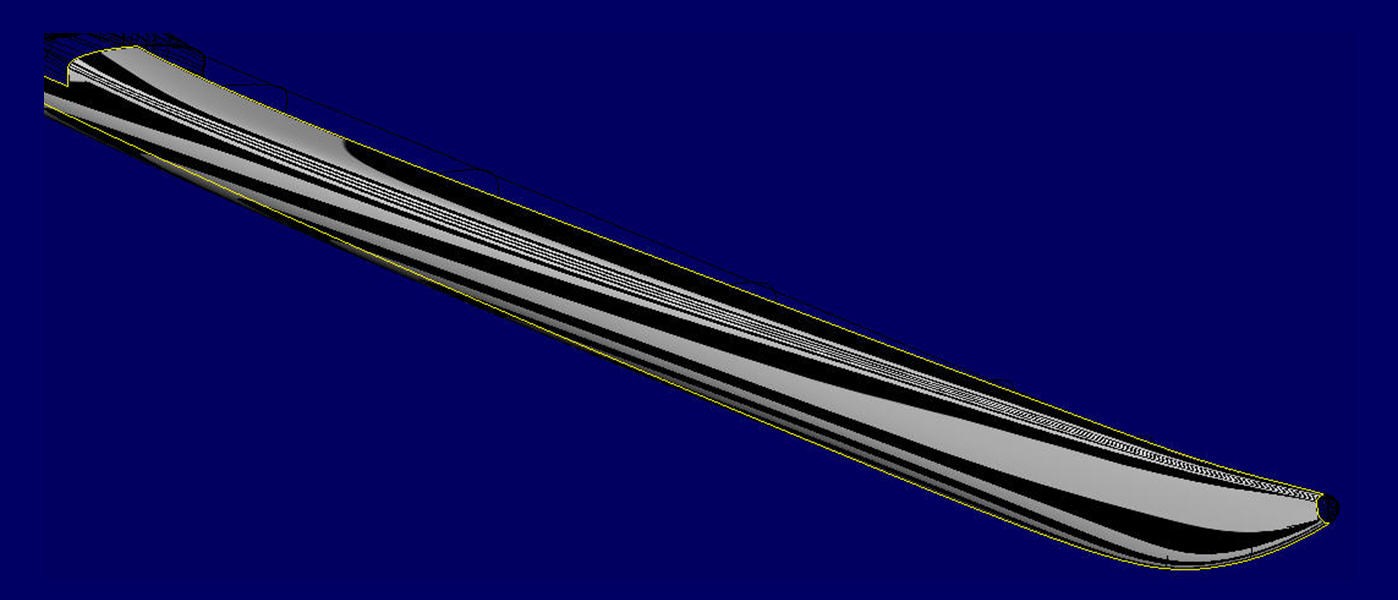
Some special approximation techniques had to be developed to transform the corrected scan data to continuous NURBS faces. The goal was to maximise the smoothness of the surfaces - reducing water resistance and to improve performance. Curvature changes had to be avoided while the surfaces had to match the scanned data as closely as possible. |
|
|
|
|
Ultimately, faces had to form a symmetrical solid part. The quality of the resulting body over all surfaces can be shown by zebra plots. The figure above shows the light lines on the most critical face, the front side of the scull. |
|
|